
One cable, five technical gates
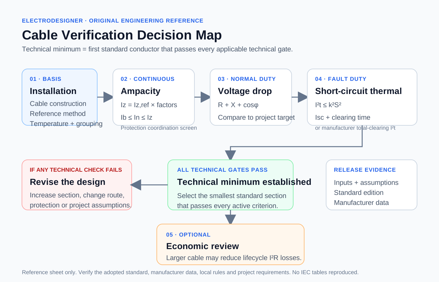
Keep each check separate
Ib ≤ In ≤ IzCorrected cable ampacity must support both the design current and the selected protective-device rating.
Iz = Iz,ref × kT × kG × kOtherStart from the correct reference method and apply only factors valid for that rating basis.
3φ: ΔU = √3 · I · (R cosφ + X sinφ)Use one-way length, conductor temperature and project/manufacturer R/X assumptions consistently.
I²t ≤ k²S²Use prospective current + clearing time or verified total-clearing device I²t.
Why a cable can pass ampacity and still fail overall
Example basis: 400 V, 3-phase, 52 A design current, Cu XLPE, method C, 65 m one-way length, 40 °C ambient, two grouped circuits, 63 A protective device, 6 kA prospective fault and 0.20 s clearing time.
This example is deliberately multi-constraint: the 16 mm² cable is not rejected by continuous load or voltage drop. It is rejected by the adiabatic short-circuit thermal check.
Before design release
What this reference sheet does not decide
- It does not reproduce or replace IEC current-carrying-capacity or correction-factor tables.
- It does not select a protective device from time-current curves or prove selectivity.
- It does not model every sheath, armour, harmonic, soil or thermal-installation effect.
- It does not replace project specifications, manufacturer data, local regulations or engineer-of-record review.
- Economic upsizing is a lifecycle decision after technical compliance, never a substitute for it.
Standards context
IEC 60364-5-52:2009+AMD1:2024 — wiring systems, current-carrying-capacity context and voltage-drop scope.
IEC 60364-4-43:2023 — protection against overcurrent.
IEC 60949 — thermally permissible short-circuit currents including non-adiabatic considerations.
IEC 60287-3-2:2012 — economic optimization concept for power cable size.
The resource explains the engineering workflow and original calculations. It intentionally does not reproduce protected standards tables.